 |
UNIVERSITY
OF CAGLIARI
Physics
Department
Complesso universitario di Monserrato
SP Sestu-Monserrato km 0.7
I-09042 Monserrato (CA), Italy |
NATIONAL
INSTITUTE FOR ASTROPHYSICS
Cagliari
Astronomical Observatory
Località Poggio dei Pini
Strada 54
I-09012 Capoterra(CA), Italy |
 |
Nichi
D'Amico - The first hand-made pulsar backend at Parkes
Modern
astronomy, like other branches of science, is continuously
developing further complex experiments, so a problem arises
when we train students and young scientists: how we can drive
them straight to the point of the essential concepts of such
sophisticated instrumentation ? In pulsar astronomy, this
can be achieved with some simple experiments, in which almost
all the technical issues can be very well addressed. Indeed,
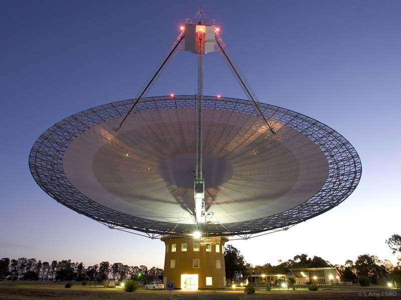
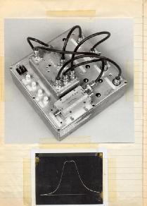
the construction at the Parkes radiotelescope (see picture
on the left) of a simple backend in 1981, represented for
me an excellent opportunity to understand the basics of pulsar
astronomy. Since then, we developed much more complex experiments,
but the basics are always the same.
|
|
| In
our early experiments at Parkers at 1.4 GHz, carried out in 1981
and 1982, Dick Manchester and myself where looking for periodicities
of the order of few tens of milliseconds -essentially we where
searching new Vela-like pulsars, but at the same time we wanted
to get rid of pulse dispersion and scattering which might be rather
strong for low Galactic-latitude distant pulsars. The hardware
that we developed for such pioneering experiments was hand-made,
and was rather simple (click on the picture to enlarge), but it
resulted to be successful in the discovery of a first significant
sample of short period distant radio pulsars. When a large radio
telescope is located close to a University site, as it will be
in our case with the Sardinia Radio Telescope, it results that
such a simple, easy-to-build, backend can be very useful for training
students, up to the point of designing and actually undertake
a pulsar observing program. |
 |
 |
 |
 |
 |
 |
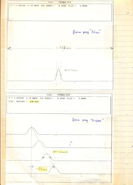
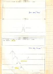
Simulations
showing the effect of Dispersion |
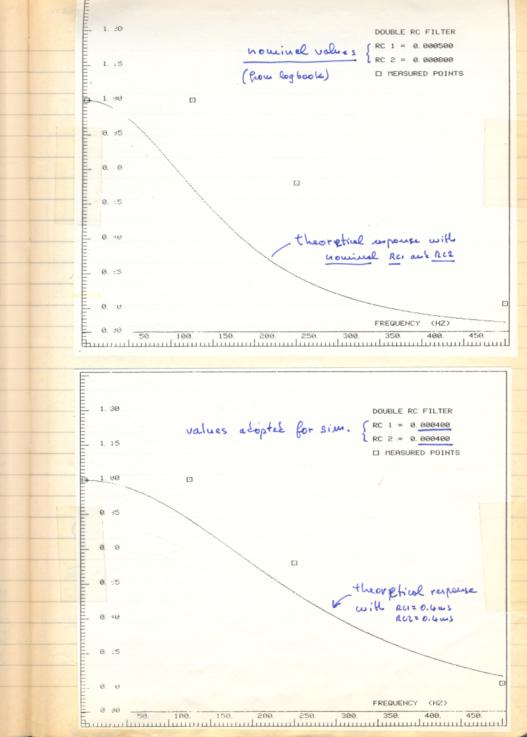
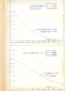
Simulation
showing the expected response of the adopted antialiasing filter
|
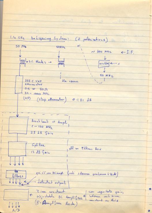
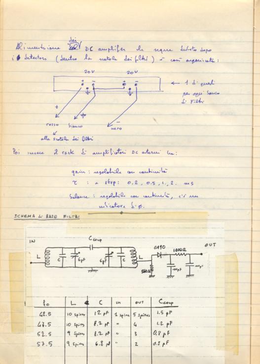
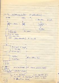
Schematics
of the filterbank connection to the IF section |
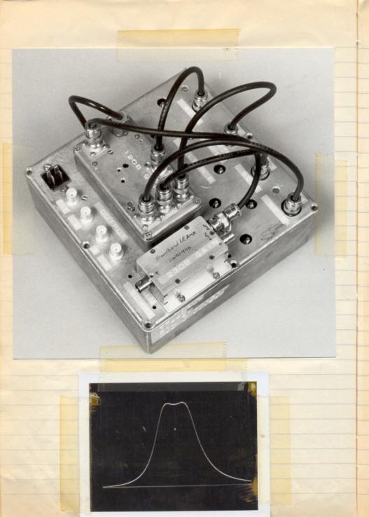
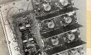
A
4 x 5 MHz filterbank, and the frequency response of each filter |
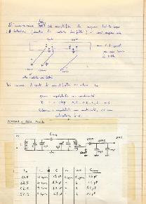
Electric
scheme of the 5 MHz filters |
|